Preliminary Research and Documentation
The following research and documentation is meant to get this project started. Please consider this a work in progress. Significant work is needed to move this project forward.
Requirements
3D software that users can create intricate 3D models, apply texture, color, lights and animation. Standard 3D modeling software applications like Maya, 3DS Max and Blender 3D are effective and offer options to create highly intricate 3D models.
Printer Software
We need to develop a software that can import these files and analyze the data. The software application needs read the contents of these files, and compute the following details:
- Number of levels
- Number of materials
- No of layers
- Width, height and volume of each part
- Structural stability
- Type of material
For the purpose of illustration, the Multi-Gantry 3D printer is used to build a lifeguard watch tower.

Figure 1 - 3D printed lifeguard watch tower.
Print Unit
When printing a 3D model, the following basic and general parts are coupled to form a print unit.
- Base plate
- Print material
- 3D printer extruder (printer head)
- Extruder rails
Each print unit can print 1 or 2 parts based on the complexity of the model. For example, if printing a ketchup bottle, one print unit prints the bottle, 1 print unit prints the cap or nozzle.
All these parts are fitted to a chassis that forms the multi-gantry 3D printer.
Chassis and Protective Cover
The chassis is made of light weight and strong material - to make it portable to remote locations. It is designed so that its length, width and height are variable and are controlled by motors from a the software application. The maximum length, width and height is 7.3 meters or 24 feet.
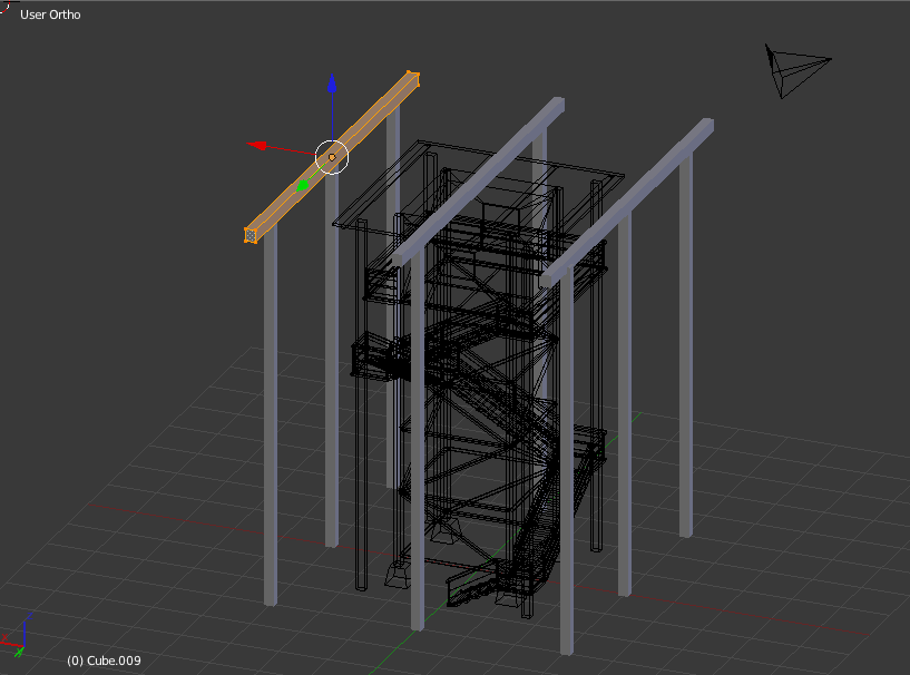
Figure 2 - 3D view of the chassis
A flexible plastic curtain-like material is attached to the chassis to protect the print area from dust and water. 5 cover the print area on four sides and the top.
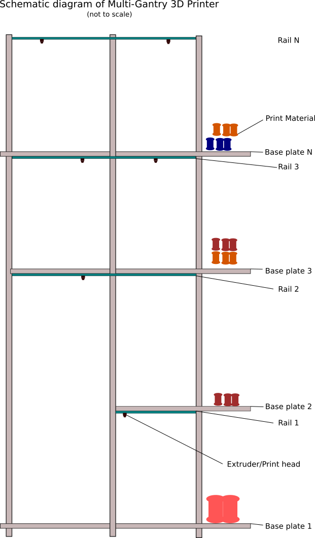
Figure 3 - Side view of the chassis
Base Plates
Each 3D printer has 1 immovable master base plate of dimension 7.3 meters x 7.3 meters (53.3 square meters) or 24 feet x 24 feet (576 square feet).
The printer also has has 11 moveable child base plates that are controlled by motors and can move vertically or horizontally depending on the shape of the model that needs to be printed. This allows printing different parts simultaneously.
The child base plates are nested within each other depending on the model. The are interlocked and can form bases of different sizes. The largest child base plate is of dimensions 7.3 meters x 7.3 meters (53.3 square meters) or 24 feet x 24 feet (576 square feet).. The remaining base plates are 2 feet smaller in length. Each of these base plates are connected by railings and motors that allow them to move horizontally and vertically depending on the computed values from the software application to create the 3D model.
The following is a top view of the base plates.
 |
 |
 |
Figure 4 - Base plates placement
Each of these plates can unite with each other to form different sizes. The maximum number of 24 feet x 24 feet bases is 5.
The following is an example of base plates placement depending on the object to be printed. In this example, the printer needs to build a wall with space for door way, window and a hole. The extruder prints the wall from the master base plate. It's nozzle turns off in the area of the doorway. When the wall reaches the lower base plate of the window, the extruder turns off the nozzle and continues to print until it reaches the upper base plate of the window. The nozzle is turned on and the printing continues along the length of the wall. When the extruder reaches the upper base plate of the doorway section, it starts printing along the full length of the wall. The upper window and doorway base plates are needed to hold the weight of the wall being printed above them.
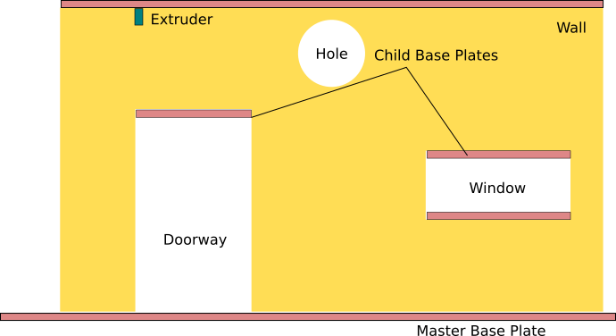
Figure 5 - 3D printing a concrete wall.
No base plates are needed for the circular hole in the wall. By masonry principles the hole's arch structure can bear the weight on the inner side of the hole.
Extruder rails
Extruder rails are rails that move vertically and horizontally depending on the values computed by the application software. The vertical movement allows them to be placed above and below the child base plates depending on the 3D model. The horizontal movement allows them to print the 3D model. These rails are controlled from the application software and operate on connected motors, similar to the base plates.

Figure 6 - Extruder rails
3D Printer Extruder
The 3D printer extruder is fitted to the extruder rails and can move horizontally while printing. The print medium is fed to the extruder from tubes connected to the chassis. Each extruder may have different properties depending on the print material. Here are a few examples of 3D extruders and print material.
| Print material | Extruder and Description |
| Plastic and polycarbonate | Standard 3D extruder that is currently used in regular 3 printers. The extruder has an option of controlling the aperture and flow of material depending on the object. For example, consider printing a rod and a pipe that have a diameter of 2 inches and a pipe. The same extruder's must be capable of adjusting the size and shape of the printed object. |
| Clay and concrete |
An extruder for clay of concrete is different from the usual printer. A construction 3D printer extruder is used for these. An example application of this extruder is building walls and platforms. When constructing a wall with spaces for doors and windows the software application must program 2 base plates. For more information, see this video. |
| Calcium carbonate |
Similar to the extruder for clay and concrete, the extruder for calcium carbonate can print minute details based on the 3D design. This extruder will be mostly used to print coral reefs. For more information, see this video. |
| Other | TBD |
The following image is an illustration of a sample extruder.
 |
 |
Licensing
This project is being developed as an open-source project with the following licensing:
- Software: GPL-3.0 - https://www.gnu.org/licenses/gpl-3.0.en.html
- Hardware, Design & other Intellectual Property: CC-BY-SA-4.0 - https://creativecommons.org/licenses/by-sa/4.0/