Preliminary Research and Documentation
Requirements
All motors and thrusters comprise of the following main parts.
- Stator - A stator is the non-moving and stationary part of a motor.
- Rotor - A rotor is the rotating part of a motor.
- Control and Movement Shaft - Unlike conventional motors, the shaft in a rim-driven thruster holds the stator and motor together and connects to movement and controls console.
Stator
A stator in a rim-driven thruster consists of a tubular casing that houses the armature and the commutator. An armature is the component of an electric motor which carries electric current. In a rim-driven motor, a number of armatures are arranged inside the tubular casing with connected to the commutator. The following is an illustration of the stator in a rim-driven thruster.
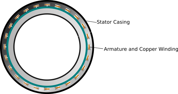
Figure 1 - Schematic diagram of a stator in a rim-driven thruster
Each armature has copper wires wound around them and connected to the commutator that facilitates the rotary movement of the rotor. The number of armatures is always equal to the number of commutators. The number of turns of the copper wire and the direction of winding determines the efficiency of the thruster.
Rotor
The rotor in a rim-driven thruster comprises of a tubular casing that houses permanent magnets arranged in a circle. The casing is molded waterproof and the magnets are completely enclosed inside the casing.
Propeller blades are attached to the inner wall of the casing as shown in the following diagram.
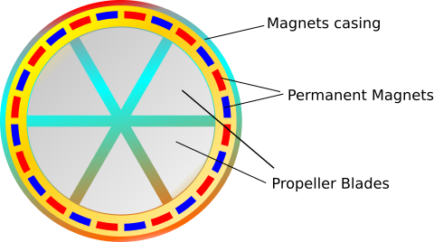
Figure 2 - Rotor of a rim-driven thruster with permanent magnets and propeller blades.
Note: Instead of multiple smaller magnets arranged alternatively in the N-S arrangement, a large ring magnet can also be used. If you use a ring magnet, the structure of the armature and copper winding directions also change.
Control and Movement Shaft
The control and movement shaft holds the rotor and the stator together. It's tubular structure houses the wires from the stator and these wires are connected to the batteries. The shaft is designed to turn clockwise and counter clockwise for maneuverability. It can be rotated manually for small boats and dinghies or controlled from a console for big boats, yachts, ships and SeaPods.
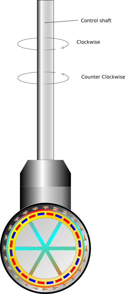
Figure 3 - Clockwise and counter clockwise movement of the control shaft.
More information on Movement and Operational Control is available here.
Licensing
This project is being developed as an open-source project with the following licensing:
- Software: GPL-3.0 - https://www.gnu.org/licenses/gpl-3.0.en.html
- Hardware, Design & other Intellectual Property: CC-BY-SA-4.0 - https://creativecommons.org/licenses/by-sa/4.0/