Preliminary Research and Documentation


Figure 1 - Underwater portion of the SWATH chassis design.
Requirements
Ballast Tanks
The chassis is designed to hold 2 sets of ballast tanks, one set at the front of each hull and one set at the back of each hull. These ballast tanks are connected to 2 water pumps that can fill or empty the ballasts when needed. The ballast tanks must be full at all times to keep the SWATH stable.

Figure 2 - Ballast tanks and hull.
Foam Liner Compartment
The foam liner compartment is a layer of foam under the belly of the SWATH concept car. The foam liner compartment ensures that the SWATH does not sink even if it is filled with water.
Rudders and Tail
Rudders are small boat-shaped rudders that can turn clockwise and counter clockwise.
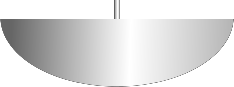
Figure 3 - Side view of a rudder
![]()
Figure 4- Top view of a rudder
Placing Rudders and Tail
A set of 4 rudders are placed at the front of each hull. A pair of tails are placed at the rear of each hull.

Figure 5 - Bottom view of the hull with rudders and tail

Figure 6 - Side view of a hull with rudders
Each rudder has a connector rod that is placed perpendicularly to the central axis of the rudder. The connector rod is then connected to a control rod that connects all the rudders together.

Figure 7 - Top view of the connector and control rods

Figure 7 - Side view of the connector and control rods

Figure 8 - Front view of the rudder, connector and control rods
Tail
The tail is a boat shaped structure that is placed at the rear of the hull away from the ballast tank. The tail is fixed and cannot turn. It keeps the craft stable and easy to maneuver.
Rudder Movement
Each rudder is fixed to the base of the hull and can turn clockwise and counter clockwise. This turning action is controlled by the control rod. The control rod can move forward and backwards, there by turning the angle of the rudders. Control rods from each hull are controlled by the central steering system.
If the control rod moves forward, the rudders turn counter clockwise.

Figure 9 - Counter clockwise movement of the rudders.
When the control rod moves backwards, the rudders turn clockwise.

Figure 10 - Clockwise movement of the rudders.
Figure
Thruster Panel
A thruster panel is designed to hold 4 rim-driven thrusters. Each thruster is controlled independently from the navigation console. It is placed between the 2 hulls and housed in the chassis. The depth of the thruster panel can be adjusted from the navigation console.
Helm (Steering Control) System
The steering control system consists of a steering wheel that centrally connects to the control rods inside each hull. Turning the steering wheel clockwise or counter clockwise turns the direction of the rudders.
- Control between one to four thrusters (electric motor-driven propellers or RIM drive motors) of up to 2 kilowatts per thruster.
- Each thruster should be able to be controlled in forward and reverse movement.
- Precise control of between one and five control surfaces like rudders and fins using marine grade stepper motors so we have directional control and they could potentially be used for stabilizing movement when stationary in the water.
- A fuel level indicator for gas or diesel.
- A battery charge level indicator.
- Control four trim tanks: We will have multiple trim tanks which can be filled or emptied with water with pumps. Two tanks will be at the front (one on the left and one on the right hull). Two tanks will be at the back (one on the left and one on the right hul). These tanks do not need to fill or empty water too fast as the trim will not need to be changed often or rapidly on each trip. They will help keep the vessel level when weight is moved around on the passenger platform. We will need pumps to move the water or air from tank to tank.
- Control four buoyancy tanks: We will have up to four buoyancy control tanks which will add/remove water/air as needed from the tanks to adjust the height of the vessel depending on whether the vessel is in movement or docked or in other situations that require the height to be adjusted.
- All pumps will run on 12, 24, or 48VDC (TBD).
- Movement sensor (9 axis accelerometer)
- Water level sensor in buoyancy tanks
- Water level sensor of the vessel relative to the ocean
- Water/air temperature sensor - Optional
- Additional sensors - Optional
- The vessel should be able to connect via API to the Ocean Builders web server when in range of the internet (specific APIs to be determined later) - BONUS
Licensing
This project is being developed as an open-source project with the following licensing:
- Software: GPL-3.0 - https://www.gnu.org/licenses/gpl-3.0.en.html
- Hardware, Design & other Intellectual Property: CC-BY-SA-4.0 - https://creativecommons.org/licenses/by-sa/4.0/